Vt Commodore Ignition Wiring Diagram, Complete Wiring Diagrams For Holden Commodore VT, VX, VY, VZ, VE, VF, 5.36 MB, 03:54, 32,796, John Amahle, 2018-08-01T19:37:41.000000Z, 19, Vt Commodore Ignition Wiring Diagram, to-ja-to-ty-to-my-to-nasz-swiat.blogspot.com, 1272 x 1800, jpeg, bcm pcm 12j swiat nasz, 20, vt-commodore-ignition-wiring-diagram, Anime Arts
3 way tele switch. One pickup, one volume, one tone; 1 volume, 1 tone, 1dpdt (dual sound bridge); Neck, neck & middle, middle, bridge split & middle, bridge.
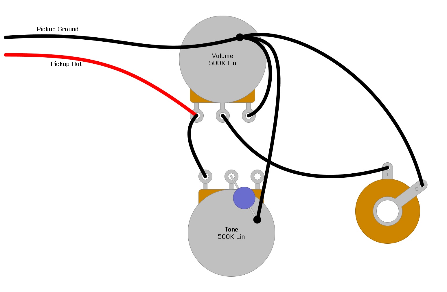
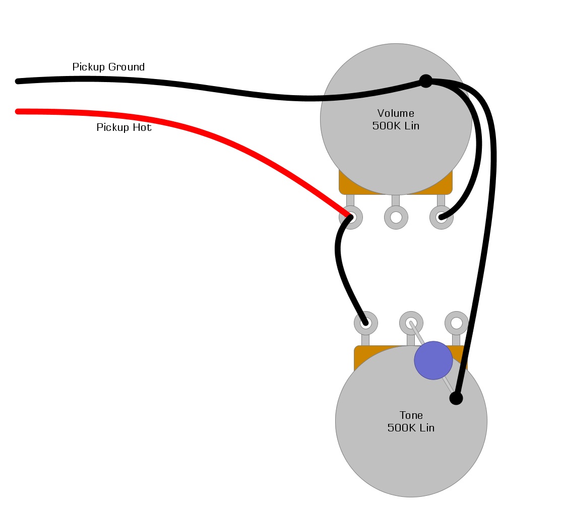
This is what turns the electricity into sound. The two contacts in question are the tip and ring of the jack cable you plug into the input on your amp. We usually call these two contacts “hot” and “ground”. Connect your neck pickup to the pigtail labeled n and your bridge pickup to the pigtail labeled b. Solder your pickup leads to the pigtails after installing this assembly. Solder your pickup's hot conductor to the pigtail inner conductor and solder your pickup's ground wire to the outer shield of the pigtail. Typical fender american standard stratocaster wiring. Pickup wiring guide gfs 5 wire humbuckers, mm pro gfs single coils, p and j bass dream 90, mean 90, ny ii, pro tube singles black = ground silver shield = ground green = + connect red to white no contact for humbucker connect to ground for single coil n s start start end end white or color = + black = ground on premium sets: Blue = bridge yellow = mid white = neck
single pickup wiring diagram volume tone - Google Search | Guitar pickups, Cigar box guitar, Box

Single Pickup Guitar Wiring Volume Pot For | schematic and wiring diagram

New Guitar Wiring Diagram Single Pickup | Guitar pickups, Custom guitars, Guitar building

Single Pickup Guitar Wiring Diagram - Humbucker Soup

Seymour Duncan Sh-4 Jb Wiring Diagram Single Pick Pickup

Volume And Tone With Single Pickup Wiring Diagram | schematic and wiring diagram

Wiring Diagrams Guitar | wiring diagram schematics - wiring diagram schematics | Guitar pickups

Single Pickup Guitar Wiring Diagram | Humbucker Soup

Hey everyone, I am building a vintage style tele with only a bridge pickup. I'm looking for a

Wiring Diagram For Single Humbucker Pickup - SALINAYANGPUNYA


