Vt Commodore Ignition Wiring Diagram, Complete Wiring Diagrams For Holden Commodore VT, VX, VY, VZ, VE, VF, 5.36 MB, 03:54, 32,796, John Amahle, 2018-08-01T19:37:41.000000Z, 19, Vt Commodore Ignition Wiring Diagram, to-ja-to-ty-to-my-to-nasz-swiat.blogspot.com, 1272 x 1800, jpeg, bcm pcm 12j swiat nasz, 20, vt-commodore-ignition-wiring-diagram, Anime Arts
Refer to figures 6 through 9 for wiring diagrams. All wiring should be in. Replacement wiring diagram if the original control is a g67bg. 8 g g670 intermittent pilot ignition controls.
Ask your own hvac question. The g67 may be mounted in any position. For g67a and g67b, refer to figures 4 through 6 for wiring schematics/diagrams and figure 7 for mounting dimensions. Refer to figure 2 through figure 5 for wiring diagrams. 5 power is wired directly to r (common) on the thermostat. Terminals 1 and 2 on the g67 are tied together internally. Wiring diagram for g67b( )! Fire or explosion hazard. Instructions to check manifold pressure:
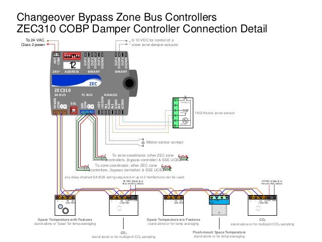
Johnson Controls Wiring Diagram - LIZAMOI

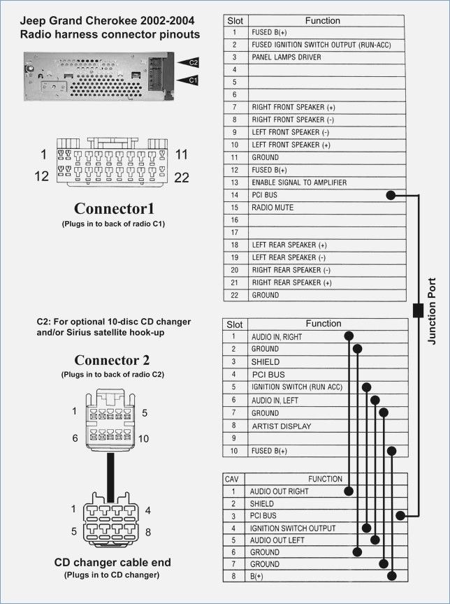
2006 Jeep Grand Cherokee Radio Wiring Diagram – vivresaville.com | Jeep grand, Jeep liberty

Free download VVDI Pro Bosch ECU adapter for BMW VW wiring diagram | Car Key Programmer
Help for Wiring diagram Bridgeport series 1

Pin on ceiling fan wiring diagram

Typical wiring diagrams (cont'd), Form rz-na i-sce, page 22 | Reznor SCE Unit Installation
1966 1967 1968 1969 VW Karmann Ghia Wiring Diagram Extraordinary Throughout Vw Beetle | Vw super

Need wiring diagram/schematic for 2004 ford ranger 4x4 v6, specifically ecm pin out and oxygen

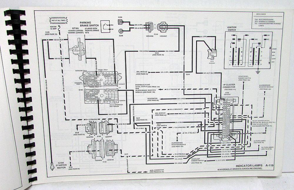
1991 GMC Top Kick Kodiak Medium Duty Electrical Wiring Diagram Service Manual

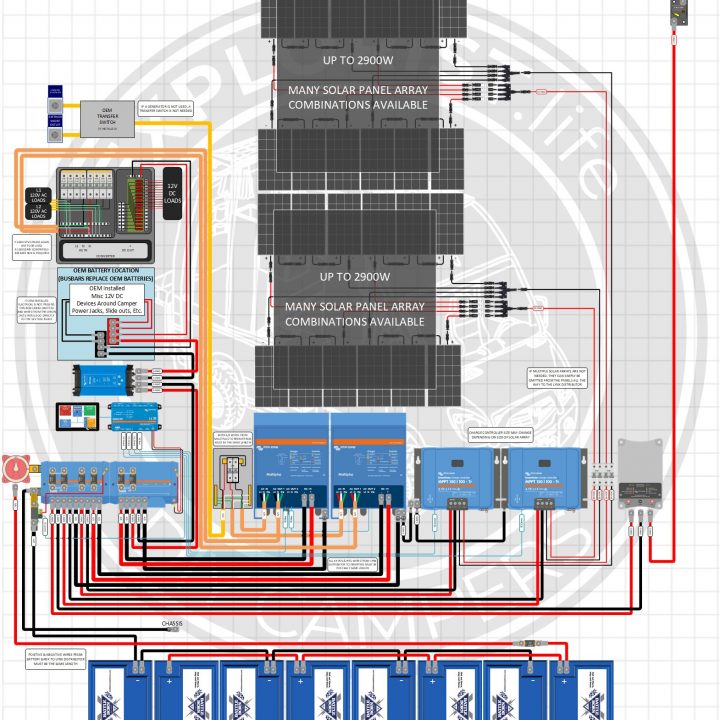
24V – 6000W – 120V/240V Split Phase Camper Solar – Wiring Diagram – EXPLORIST.life


